A lap joint flange can simplify bolt-hole alignment, but an incomplete specification can turn that advantage into a purchasing problem. Buyers may receive a flange and stub end that look suitable yet do not fit correctly. I start with how the pair works, then check dimensions, materials, and inspection requirements together.
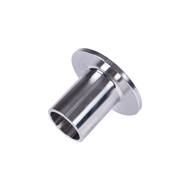
A stub end and lap joint flange form a two-piece connection. The stub end is butt-welded to the pipe and provides the wetted passage and gasket seating face. The separate flange sits behind the stub end’s lap and transfers bolt force to the joint while allowing rotational alignment before tightening.
I find this connection easier to evaluate when I separate convenience from engineering suitability. Rotating bolt holes can help during assembly, but they do not establish pressure capability or fatigue performance. The following checks help me build a clearer purchase specification without treating separate components as interchangeable.
How Does a Lap Joint Flange Work, and When Would I Specify It?
I often see buyers focus on the rotating flange because it solves an obvious installation problem. However, that feature is only one part of the decision. I also consider maintenance access, alloy cost, and service conditions before adding this connection to a procurement package.
I consider a lap joint flange where repeated disassembly, easier bolt-hole alignment, or selective use of an expensive wetted alloy offers a practical benefit. The stub end carries the gasket seating surface, while the backing flange applies clamping force. A qualified engineer should confirm suitability for the actual pressure, temperature, and loading conditions.
I separate the sealing function from the clamping function
The stub end is the pipe-connected component. Its barrel is butt-welded to the pipe, and its outward-facing lap provides the surface against which the gasket seals.
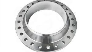
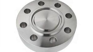
The backing flange fits around the stub end barrel and bears against the back of the lap. It is not welded to the pipe. Before the bolts are tightened, the flange can rotate independently to align its bolt holes with the mating connection.
I make one distinction clear in purchasing discussions: the flange can rotate for alignment, but the completed joint is not a swivel connection. The assembly should not move freely during operation.
The flange also does more than hold bolt holes in position. It transfers bolt loading into the lap, so its material, dimensions, and supporting contact geometry remain important.
I look for a genuine maintenance or assembly benefit
I see three common reasons to evaluate this arrangement:
- Maintenance teams need repeated access. A removable joint can help where equipment or piping sections require periodic separation.
- Installers need easier bolt-hole alignment. The backing flange can rotate without requiring the welded pipe section to rotate.
- The wetted material is expensive. The stub end can use the required corrosion-resistant alloy while the backing flange uses a separately approved material.
The alignment advantage does not correct pipe misalignment. I would not accept a proposal that relies on bolt tightening to pull poorly aligned pipework into place.
I compare alloy savings against the complete purchase cost
A stainless steel stub end does not always need the same grade as its backing flange. For example, a buyer might ask an engineer to evaluate a 2507 stub end with a 304 stainless steel backing flange.
I treat that combination as a proposal requiring approval, not a standard recommendation. The backing flange still faces external conditions, temperature exposure, and mechanical loading. Material differences can also affect corrosion compatibility and thermal behavior.
For a stainless steel lap joint flange package, I compare the total cost of both components, inspection, documentation, and assembly. I do not assume that reduced expensive-alloy content automatically produces the lowest installed cost.
How Do I Compare a Lap Joint Flange vs Slip On Flange and Weld Neck Flange?
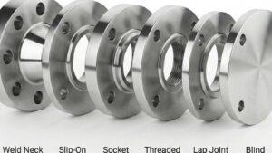
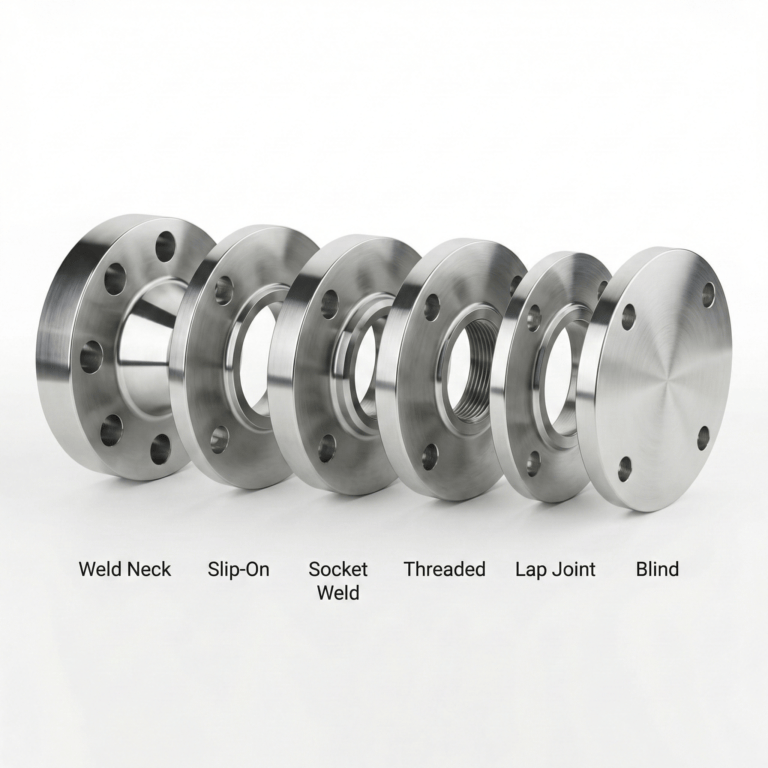
I find flange comparisons misleading when they reduce the decision to “low pressure” versus “high pressure.” A pressure class does not describe every loading condition. I compare the connection method, assembly convenience, and cyclic-service suitability separately so that purchasing does not confuse a rating label with complete joint performance. For the wider flange family, see the six most common flange types in process piping.
In a lap joint flange vs slip on flange comparison, I distinguish the freely rotating backing flange from a flange welded directly to the pipe. Weld neck flanges provide a more gradual load transition and are generally favored for demanding cyclic duties. The approved design must establish the suitability of each complete connection.
I use a comparison table without treating it as a design approval
| Purchasing consideration | Stub end with backing flange | Slip-on flange | Weld neck flange |
|---|---|---|---|
| Pipe connection | The stub end is butt-welded to the pipe; the flange remains separate. | The flange is typically attached with internal and external fillet welds, subject to the governing requirements. | The flange neck is butt-welded to the pipe. |
| Bolt-hole alignment | The flange can rotate before tightening. | The hole orientation becomes fixed after welding. | The hole orientation becomes fixed after welding. |
| Gasket seating surface | The gasket seats on the stub end lap. | The gasket seats on the flange facing. | The gasket seats on the flange facing. |
| Expensive-alloy allocation | The wetted stub end and backing flange can use separately approved materials. | The flange material must suit its exposure and design requirements. | The flange material must suit its exposure and design requirements. |
| Cyclic loading | The lap and backing arrangement require particular attention. | The welded attachment geometry requires fatigue consideration. | The neck offers a more gradual transition for load transfer. |
| Procurement complexity | Two components must be matched. | One flange must match the pipe and mating connection. | The flange bore and weld end must match the pipe specification. |
I do not describe this connection as inherently low-rated
ASME B16.5 includes pressure-temperature ratings for applicable flange materials and classes. A lap joint flange is not automatically assigned a lower rating merely because it is loose behind a stub end.
However, I do not use the flange marking alone to establish the allowable pressure of the assembly. The stub end wall, lap geometry, materials, gasket, bolting, temperature, and governing piping rules all matter.
I also check size and class availability in the applicable standard edition. I avoid assuming that every flange type is available in every combination of nominal size and pressure class.
I keep fatigue claims qualitative unless a design assessment supports them
For significant vibration, repeated thermal cycling, or substantial bending loads, I ask the responsible engineer to review the joint arrangement explicitly. A weld neck connection is generally the stronger starting point for these demanding conditions because of its load-transfer geometry.
I do not quote fatigue multipliers. Any fixed ratio hides differences in geometry, loading, fabrication, and acceptance criteria.
My purchasing question is more useful: Has the selected connection been approved for the actual service, rather than only matched to a pressure class?
How Do I Match the Stub End Pattern to the Lap Joint Flange?
I regard component fit as a major procurement risk because two individually acceptable parts can still form an unacceptable pair. A missing pattern designation or an unsuitable bore radius can cause trouble after delivery. I therefore review the stub end and flange as one dimensional interface.
I match the stub end’s barrel diameter, lap dimensions, root radius, length, and wall thickness to the backing flange and pipe specification. Short and long patterns need explicit identification. The flange bore and contact geometry must clear the lap root correctly, and the gasket must seat on the stub end face.
I specify the pattern rather than relying on a catalog label
Short-pattern stub ends are commonly associated with MSS SP-43 and corrosion-resistant, relatively thin-wall piping applications, including Schedule 5S and 10S arrangements. ASME B16.9 is a common reference for wrought butt-welding stub ends, including long-pattern products.
However, I do not let the standard name replace the dimensional specification. Supplier catalogs and product descriptions can differ in how they present pattern options.
I state:
- The applicable product standard and edition.
- The required short or long pattern.
- The overall length or approved drawing reference.
- The nominal size and specified wall thickness.
- The lap diameter and interface dimensions where the project requires explicit confirmation.
A longer pattern can provide additional axial space for welding access or future cutback, but I do not assume that length alone establishes suitability for thicker pipe or more demanding service.
I check the bore and lap-root clearance together
The flange bore must allow the component to fit over the stub end barrel. Its lap-side geometry must also accommodate the stub end’s root radius.
This interface deserves attention because the backing flange needs to bear correctly against the lap. If an incompatible edge contacts the curved root first, the pair may not seat as intended.
I therefore ask for dimensional confirmation of the following features:
| Interface feature | What I ask the supplier to confirm |
|---|---|
| Barrel outside diameter | The flange bore provides the specified fit and clearance. |
| Lap root radius | The backing flange clears the radius without unintended interference. |
| Lap outside diameter | The lap and backing surface provide the approved support geometry. |
| Stub end wall | The weld end matches the approved pipe connection requirements. |
| Gasket seating face | The finish and usable seating area match the selected gasket requirements. |
I do not substitute a slip-on flange without approval
A standard slip-on flange is not automatically interchangeable with a purpose-made lap joint flange. Its bore edge, facing, and contact geometry may not suit the selected stub end.
Some suppliers use Type A, Type B, and Type C terminology for different stub end configurations. I treat these as descriptions that require a drawing, not as universally sufficient ordering codes. In particular, I do not assume that a supplier’s type designation is a clause or classification within ASME B16.9.
The gasket belongs on the stub end lap, not on the backing flange. I make that distinction visible on the assembly drawing because it affects facing requirements and inspection.
For dimensions outside the applicable standard’s coverage, I request an engineered drawing and a clear design basis. A manufacturer’s ability to produce a large diameter does not make that product standard-covered.
What Should I Include in a Lap Joint Flange RFQ?
I find that incomplete inquiries create more uncertainty than difficult material grades. When wall thickness and pattern are missing, suppliers may price different products against the same description. I use a component-by-component RFQ so that quotations can be compared on a consistent technical basis. The general inquiry fields for fittings and flanges are in the buying guide.
My lap joint flange RFQ identifies the size, stub end wall and pattern, separate material specifications, flange standard and pressure class, quantities, facing requirements, and inspection scope. I attach an approved drawing for special interfaces. I also request a written list of deviations so that missing details do not become silent substitutions.
I separate the two components in the purchase description
Even when I buy an assembled commercial “set,” I list the stub end and flange separately. This approach makes quantities, material requirements, and pricing easier to audit.
| RFQ field | Information I include |
|---|---|
| Nominal size | I state NPS or DN and identify the governing dimensional system. |
| Stub end wall | I state the schedule or specified wall thickness and the pipe match requirement. |
| Stub end pattern | I identify the short or long pattern, product standard, and required dimensions. |
| Stub end material | I state the applicable material specification and grade. |
| Construction | I identify the required seamless or welded construction and applicable product classification. |
| Flange material | I specify the backing flange material separately. |
| Flange rating | I state the dimensional standard, pressure class or PN designation, and required type. |
| Quantities | I list the number of stub ends and flanges individually. |
| Weld end and facing | I identify the weld preparation and gasket seating surface requirements. |
| Surface treatment | I state the required cleaning, pickling, passivation, or finish. |
| Inspection and records | I define dimensional checks, material records, testing, and traceability requirements. |
| Drawing references | I include approved drawings for nonstandard or specially controlled features. |
For material descriptions, I might identify ASTM A403 WP316L for a stainless steel stub end and ASTM A182 F304 or F316L for a forged backing flange, where those specifications are appropriate. The grade choice itself is covered in 304 vs 316L fittings.
In ASTM A403, the class suffix after the grade, such as WP316L-S or WP316L-W, identifies seamless or welded construction and the related examination requirements, so I state the full designation in the order.
I keep ASME and EN descriptions internally consistent
If the project uses ASME requirements, I specify the applicable ASME dimensional standard and class. If it uses EN requirements, I identify the relevant EN 1092-1 type, PN designation, material, and compatible collar or stub end arrangement.
I do not treat Class 150 and PN 16 as automatically interchangeable. A similar nominal service description does not establish dimensional or pressure-temperature equivalence.
I ask for a documented manufacturing route
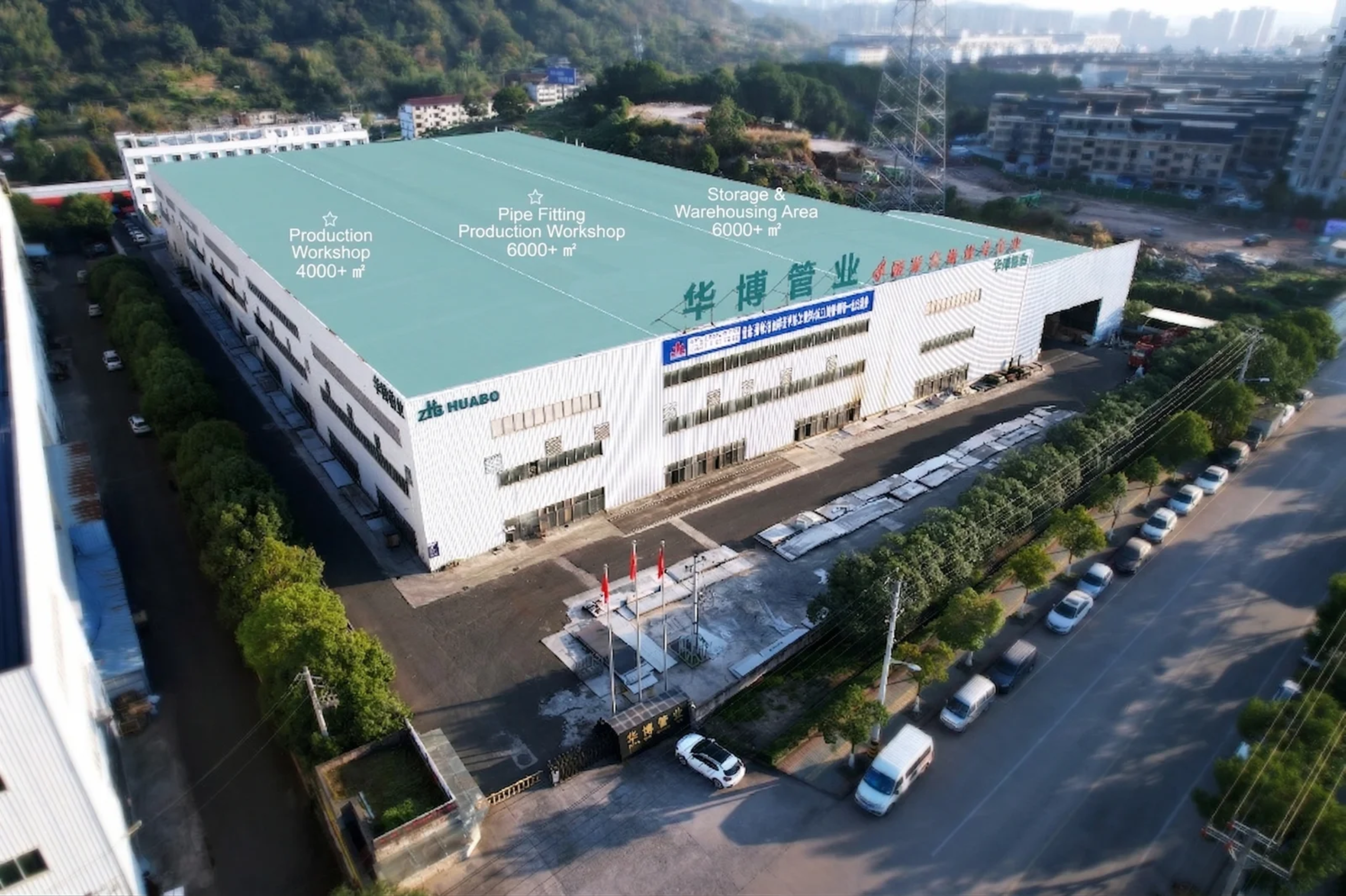
For a stainless steel stub end from Huabo Pipe Industry Co., Ltd., the route is cold formed → solution annealed → bevel machining and sizing → surface finishing by polishing, pickling, sand blasting or sand tumbling.
For a forged lap joint flange from the same supplier, the route is forged → solution annealed → machined and drilled → pickled and passivated.
Heat treatment and acceptance requirements still depend on the specified alloy and product standard, so I confirm them in the order documents.
Huabo Pipe Industry Co., Ltd. makes stub ends to ASME B16.9 dimensions and lap joint flanges to ASME B16.5, and can match the two as a set for a project specification.
I define inspection instead of requesting “all tests”
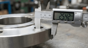
My inspection request focuses on measurable acceptance criteria. I identify the dimensions that need recording, the required material traceability, and any specified nondestructive examination.
I also clarify whether pressure testing applies to an individual component, an assembled spool, or the installed system. A loose flange does not provide a closed pressure boundary by itself.
The two omissions I check first are stub end wall thickness and pattern length. Both can change the delivered dimensions and price without being obvious in a brief quotation description.
Frequently Asked Questions
Does the gasket seal against the flange or the stub end?
The gasket seals against the stub end’s lap face. The backing flange bears behind that lap and transfers bolt force into the assembly. I therefore specify the stub end’s gasket seating finish separately from the backing flange’s surface treatment and general machining requirements.
Can I use different stainless steel grades for the two components?
Different grades can be considered because the backing flange is normally outside the process-wetted passage. I still require engineering approval for external corrosion exposure, temperature, mechanical properties, and material compatibility. I do not select a cheaper flange grade solely because it does not normally contact the fluid.
Is a short-pattern stub end always the better-value option?
I do not assume that a shorter component provides the best overall value. It may reduce material use, but welding access, equipment clearance, maintenance cutback allowance, and the approved dimensional standard also matter. I compare the specified pattern against the actual installation requirements before accepting a lower quotation.
Can I replace a backing flange with a standard slip-on flange?
I would not approve that substitution without a dimensional and engineering review. The bore edge and lap-root clearance may differ, and the flange may not bear correctly against the stub end. A matched, purpose-specified combination is safer to purchase than an assumed interchangeable pair.
Is this connection suitable for strong vibration or frequent thermal cycling?
I do not make it my default choice for severe cyclic service. The lap, backing contact, and welded stub end need a service-specific assessment. A qualified piping engineer should review vibration, thermal movement, support conditions, and bending loads before approving the connection arrangement.
Conclusion
I evaluate a lap joint flange as one part of a matched connection, not as an isolated catalog item. The main benefits are easier alignment, maintenance access, and selective use of expensive alloys. Reliable procurement depends on matching the stub end pattern, wall, lap geometry, materials, and inspection scope. For a quotation from Huabo Pipe Industry Co., Ltd., I recommend submitting separate component specifications and an approved drawing where needed, with application-specific decisions confirmed by a qualified engineer.